The sequence between the physical and logical network elements is displayed below.
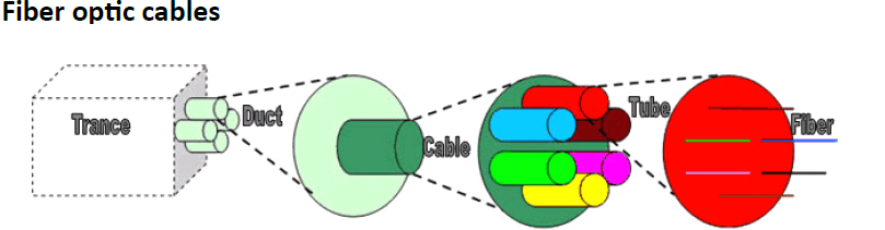
There is great diversity in the arrangement of:
•The number of fibers in a tube.
•The number of tubes in a cable.
•The number of ducts in a trench.
In order to differentiate the fibers as clearly as possible each tube in a cable and each fiber in a tube is colored.
Enclosure
Because there are limitations with regard to the length of fiber optics, fibers must be spliced around a certain unit of length in an enclosure (GCO). This casing is located in a so-called Manhole or Handhole:
Through this enclosure it is possible to perform a weld to a location (POP) or a client. Excess length of the glass fiber is a measure to enable work for out-welding.
Frame
The frame enables the further distribution of data provided to connected machinery.
Regardless of the type of frame, functionally speaking there is always a subdivision of a splice shelf unit and a patch panel.However, it may be the case that physically both the splice shelf unit and the patch panel are combined.Glass fiber enters a splice shelf unit and is subsequently connected to the patch panel via patch cables (pigtails). A connection with other patch panels or with other machinery (for instance a MUX) can be made from a patch panels.
Occasionally it is the case that glass fibers are being welded directly within a splice shelf unit (a so-called RASS splice).
Subdivision Splice Shelf Unit / Patch Panel
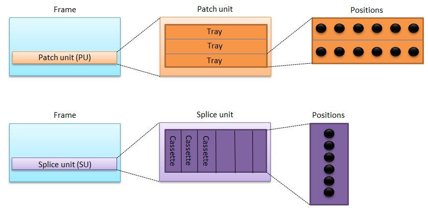
The picture above depicts the subdivision specific to an Optical Distribution Frame (ODF). However, the systematics in the subdivision is applied in the same manner to every type of patch panel or splice shelf unit and is represented in Cocon.
The logical architecture
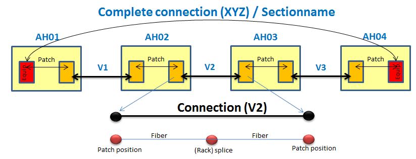
The picture above depicts the logical hierarchy the way it functions with fiber management in Cocon. It is important to note here the difference between a connection and a point of connection.
|
|
© Speer IT B.V. 1999-2018 |