In this screen the data regarding splices in an enclosure are maintained.
As soon as this screen is opened up the data of the first enclosure are displayed.
You may search on location or on enclosure.
The screen consists of two subscreens
•Splice cassette details
•Other properties
In the "Splice cassette details" subscreen the existing splices are displayed and new splices may be added.
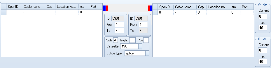
To enter a splice, select the leftside- and the rightsidecable. Then specify what fiber(series) are spliced unto each other.
The follow fields be be used to specify the splice:
From |
The first fiber number of this series. |
To |
The last fiber number of this series. |
Side |
The side of the enclosure, which has the spliced series. Values allowed: A / B |
Height |
The height of the cassette, unto which the spliced series are placed. On the right side of the screen the currect, last taken, position is shown of both the A and B side. Attention: If height 1, 2 are taken, 3,4,5 are free and height 6 is taken, the last taken height shown is 6. The field 'max.' shows the maximums amount of heights on this enclosure type. |
Position (Pos) |
De eerste groefpositie op de cassette waarop de serie geplaatst is/dient te worden |
Cassette |
Het type cassette dat gebruikt is/dient te worden. |
Splice type |
Het type verbinding wat gebruikt is/dient te worden. U kunt hier kiezen voor het type: splice, no-splice of splitter. |
Below in the grid alle existing and planned splices are shown. By selecting a splice (series), the details are also shown in the top part, in the Splice casette details screen.
Here you can edit a splice, and save the changes by clicking ![]() the button.
the button.
The following actions may be taken from this screen:
|
Through the yellow input field you may search for a (part of the) location name / enclosure id. |
|
Search for the location name. |
|
Search for the enclosure id |
|
Navigate the cable types |
|
Displays a report on all ducts in a handhole with any possible relations with cables and slacks (cables in storage). |
|
Displays a list of files linked to the enclosure. |
|
A report of all changes is displayed that occurred on the splices in this enclosure. |
|
Displays any available GCO-autocad-drawing. This drawing is saved in the directory as indicated at the installation of Cocon. The name of the file equals that of the enclosure, with the dwg extension. |
|
Changes the name of the enclosure. For this, the Enter point screen is called up. |
|
View the cable usage of the selected cable. The Report on usage per cable screen is displayed. |
|
Shows a report on usage by customers of all involved cables. |
|
View the connection of the first fiber from the selected cable (fiberseries). The Connection report screen is displayed. Depending on the splice status, either the connection report - present, or the connection report - future is displayed. |
|
Display the enclosure in the geography. |
|
Note: This is only shown on a recovery splice. |
|
Maintain questions on this project. |
|
Import the linked .csv file and edit the splice information with this. You can also change the primary fiber (only ftth networks and splices). The file needs to be placed in the linked map for this GCO. The GCO may not be in status 2; reserved for removal. |
|
You use this button if you want to record that a handhole is opened or closed. You may enter a description of the manual. The actions are recorded in the history. |
|
By clicking here a cross is placed in the geography on a certain distance from the selected position. You will be asked for a distance in meters, after which the connection is followed from the selected position until the distance entered has been reached. This way, you can perform a quick search for a malfunction, for instance. |
|
Do not remove previous measurement in the geography. |
|
Create splice-scheme in HTML-format |
|
Create future splice-scheme in HTML format |
|
Make splice scheme file for printing only. |
|
Make future splice scheme for printing only. |
|
Choose 1 or 4 tabs for Excel-sheets. |
The following actions may be taken from the subscreen "Splice cassette details":
|
Refresh the data in the screen. Any changes made are canceled. |
|
Generate again all heights, based on the complete filling and sequence of the detail lines of the splices in the screen. |
|
With this button selected cables/ fibers will be highlighted. By pressing the button once, the selected fibers are presented. By pressing the button twice, the selected cables are presented. By pressing the button three times, the selected highlight is reset. |
|
If there should be future splices, and these are selected, this button can save work and time. Cocon will split the existing series, the series which have to be removed will be served for removal , the remaining spare - fibers will be reserved in the right cassette and determine the correct cassette for the new splice. The new splice will also be made. All these activities are registered for the selected project and the related default executive contractor. |
|
By entering fiber series in the top part of screen 2 and then pressing this button, a new splice is created. For this purpose the Confirm splices screen appears, again displaying the data of the splice to be created, before the splice is actually saved. |
|
Confirm a splice selected for removal. This button is only visible at the for removal selected splices. |
|
Confirm a selected splice. This button is only visible at selected splices. |
|
Use this button to remove the currently selected splice. This button is only visible at splices in use. |
|
Cancel selected splice. This button is only visible at selected splices. |
|
Reserve splice for removal This button is only visible at status: 'in use'.
Note! When a splice will be reserved for removal, Cocon will ask if the section names which are related to the splice, also should be reserved for removal. |
|
Cancel the reservation for removal. This button is only visible at selected splices. |
|
Use this button to change the data of a splice (side/(type)cassette/splice status), in order to split splices or to remove existing splices and entering those again. |
|
The splice shelf data are turned around, i.e. the data of the selected splice to the left of the screen are replaced to the right and vice versa. |
|
Use this button to split the current splice series. The Split splice screen is displayed. |
|
The splitting of a series of 8 or 12 fibers. If a splice cassette of 12 fibers is present then the button for splitting the 12 fibers will be active. If no splice cassette of 12 fibers is present then the button for splitting the 8 fibers will be active. |
|
Use this button to merge all selected series. If the splice series has been divided over 2 or more records this function ensures that another record appears for the entire splice series. |
|
Create all splices for FTTH network at once. Fill in all fields as usual but instead of pressing OK just press this button. |
|
Add line (ins). |
|
Change the splice date in today. |
|
Change the existing splice indicator to true. |
|
Note: this button is not accessable for al our cutomers |
|
Note: this button is not accessable for al our cutomers |
|
Detail status can be selected and accepted for selected splice(s). |
|
Here you can enter a description. Previously entered descriptions can be selected. |
|
Here you can select the right contractor. |
|
Select the splicer to which the work is assigned. |
|
Select the date when the work should be ready. |
|
Here you can indicate whether the work should be done in the night. |
|
Attach the input / Process the changes. |
The following actions may be taken from the subscreen "Other Properties"
|
In this screen the changes are saved. |
|
Cancel any changes made and again display the enclosure. |
! |
Comments which are posted to an object will be displayed in this screen. When there is a comment available there will be an exclamation point on the top of the 'insert splices' screen. |
Yellow background color
The existing splices on both ends of a cut cable can be reserved for removal or connection to the new (created by cutting) cable.
These splices are displayed with a different background color in the splice screen.
Also, a notification will be presented when generating a splice scheme, stating the splices do not have to be removed and connecting the splices is already done.
Tips
* A feature is available for displaying the available fibers per cable. Select a cable in the left or right grid with cables and click the right mouse button. Now the available fiberseries will be shown. The list disappears again when you click
anywhere in the grid.
* By selecting multiple lines, multiple splices can be deleted or planned.
* The detail lines of the splices may be sorted by clicking on the header of the column concerned.
* To insert a splitter first you must select "Splitter" as splice type. Now, on the left of the screen, one fiber can be selected. Next, on the right side fill in the correct number of fibers that should be spliced.
Last edited: 05-10-2017
|
|
© Speer IT B.V. 1999-2018 |